DIY LED BACKPLATE
Welcome to a guide on how to create a DIY Bluetooth RGB LED Backplate. Have a messy bunch of cables that you want to hide away? Or simply want to add some colors to your rig? Well, if you have a 3D printer, you are in luck.
Yes, it is possible to create a transparent (or translucent) 3D print, then stack an opaque layer on top to create a silhouette – Throw some LED lights behind, and we get a nice backplate. But just how does this “dual-layer” 3D print work? What are the parts required? Here is a sharing of my own build, read on to find out!
TABLE OF CONTENTS
 Section A Section AThe Basics |
 Section B Section BDIY Steps |
 Extra ExtraUseful Bits |
 Closing ClosingWhat’s Next? |
THE BASICS
All right, let us now get started with the basics – What are the parts used, software, and a couple of things to look out for.
PARTS & MATERIALS LIST
| Part/Material | Get From eBay |
| Translucent / Transparent Filament | Click Here |
| Any opaque filament. Preferably black. | Click Here |
| 12V RGB LED Strip | Click Here |
| LED Bluetooth controller | Click Here |
| 4 pin LED solderless connector | Click Here |
| 4 pin Molex to DC plug (or CRJ Male SATA to DC plug) | Click Here |
Yep, that’s not a lot of parts thankfully.
SOFTWARE
Just for the record, here is the software that I used.
- Matter Control – Not as capable as other CAD software, but easy to use.
- Ultimaker CURA – Who doesn’t know this one!?
STL FILE DOWNLOAD
Click here to download the files, just a couple of things to take note:
- There are 2 STL files in the zip archive.
- The first one is the plate measuring 140 X 80 X 2 mm… This is pretty much just a dummy. Please create one yourself, with the image that you want to use.
- The second file is the enclosure to hold the plate and LED strip.
A FAIR REMINDER & DISCLAIMER
Well, we are still dealing with electronics here, even though there is no soldering required. If you are not confident with opening up your own computer and dealing with the technical stuff – Consult a professional electrician instead. Do this project at your own risk, Red Dot Geek is not liable for your screw-ups. 😛
DIY STEPS
Now that we have all the basics out of the way, let us get on with the build – Here’s how I built the LED backplate.
STEP 1 – MEASUREMENTS
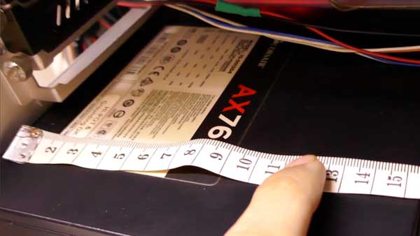
Captain Obvious to the rescue! Measure the space for the backplate to be placed on. I used an empty space on top of the power supply, and it had a good 160 X 85 X 140 mm. But I figured it will be good to give some space allowance, thus decided with a plate size of 140 X 80 mm instead.
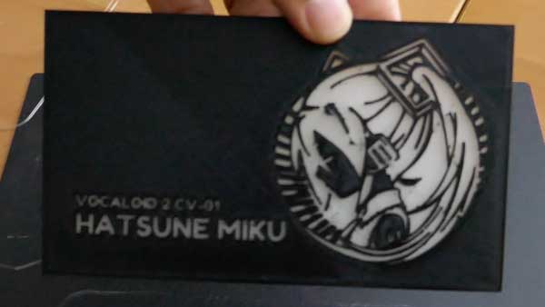
STEP 2 – DESIGN THE PLATE
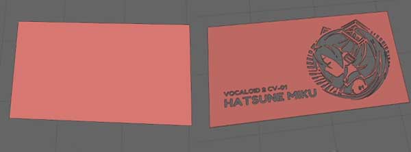
This step may seem to be rather complicated, but it is actually pretty simple…
- I started with two 140 X 80 X 1 mm rectangular pieces.
- The first piece is just a solid rectangle, to be placed at the bottom and printed with a translucent filament.
- The other piece will have designs embedded in it, to be placed on top and printed with an opaque filament.
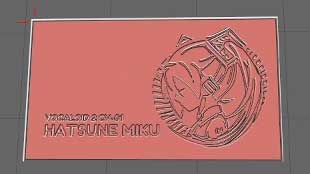
- Next, I looked for a nice design online – Silhouette and line art seems to work the best.
- Convert the image to a component, subtract it from the top rectangular piece.
- Combine the 2 pieces together – Solid piece below, the designed piece on top.
- Finally, export the model and throw it into CURA for slicing.
STEP 3 – SLICE & ADD PAUSE
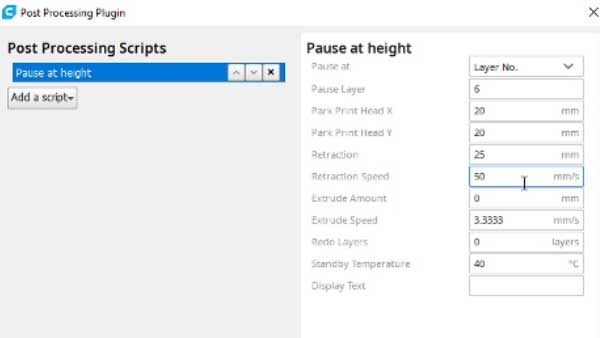
No, we do not need a dual extruder 3D-printer to do multi-color (different filament) prints. Special thanks to this YouTube tutorial by CHEP, here’s a small trick in CURA to make the printer pause during mid-print:
- Extensions > Post Processing > Modify G-Code.
- Add Script > Pause At Height.
- At 0.2mm per layer print, the 140 X 80 X 2mm plate had 10 layers – So yep, making it pause at layer 6 for a filament change makes sense.
- As for the rest of the settings, it will be good to retract some of the filament during the pause, just to make the change easier.
STEP 4 – PRINT IT!
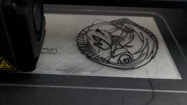
The print started with a translucent filament first, then paused at layer 6 as instructed. Simply switched to use the opaque filament at this time and continued printing.
Sadly, a budget 3D printer did not produce the best prints… A little post-print clean up (manual clipping and sanding) did the magic.
STEP 5 – THE ENCLOSURE
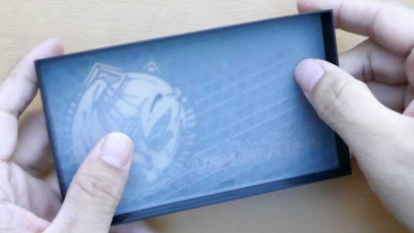
Next stop, the enclosure. Nothing special with this one, just “4 walls and a small notch in front”. Printed it, and inserted the plate inside – The print had a pretty tight fit, but some light sanding around the edges did the job.
STEP 6 – THE ELECTRONICS
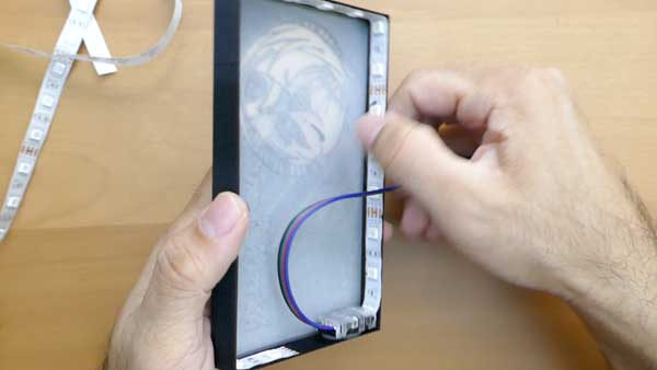
The rest of the build is pretty straightforward, just sticking the LED lights around the inner frame of the enclosure.
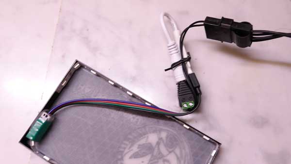
The cables are kind of funky though… LED strip > LED connector > Bluetooth Controller > Molex to DC plug > Computer power supply. Contemplated to cut the wires short and solder them together, but got lazy with a cable tie in the end.
STEP 7 – LET THERE BE LIGHT!
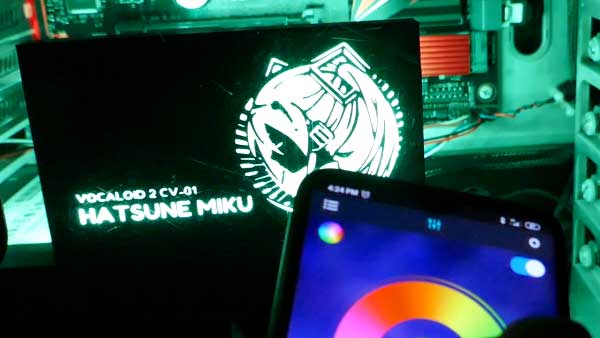
All that’s left is to download the LED app via scanning the QR code – Then simply put the backplate into the computer and watch it glow.
USEFUL BITS
That’s all for this guide, and here is a small section on some extras and links that may be useful to you.
THE YOUTUBE VIDEO
LINKS & REFERENCES
- Molex 4-pin Peripheral Power Connector Pinout – Lifewire
- SATA 15-Pin Power Connector Pinout – Lifewire
- Where to find images with a transparent background? Note – Some of these images may be copyrighted. Ok for personal use, do not sell nor make commercial 3D prints.
WHAT’S NEXT?
Thank you for reading, and we have come to the end of this guide. I hope this has helped your project, and if you have anything to share with this guide, please feel free to comment below. Good luck and may the cyber force be with you.